
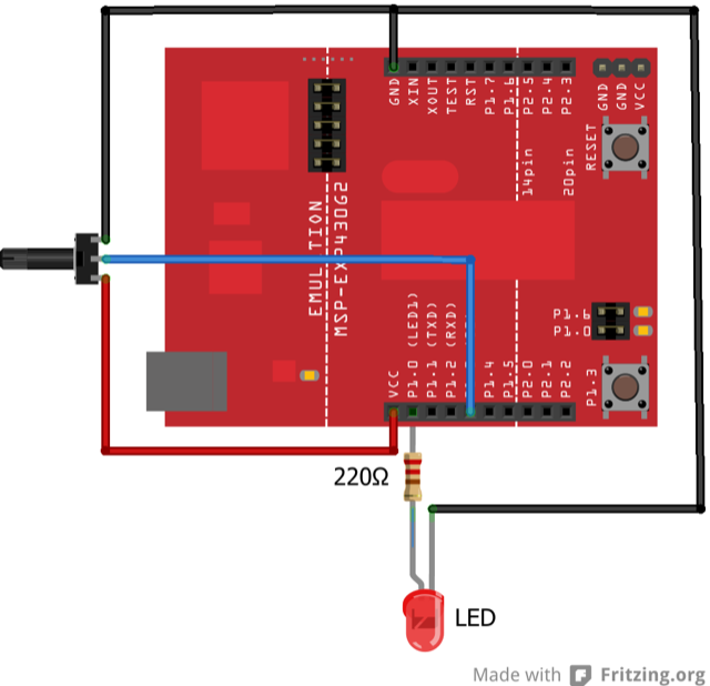
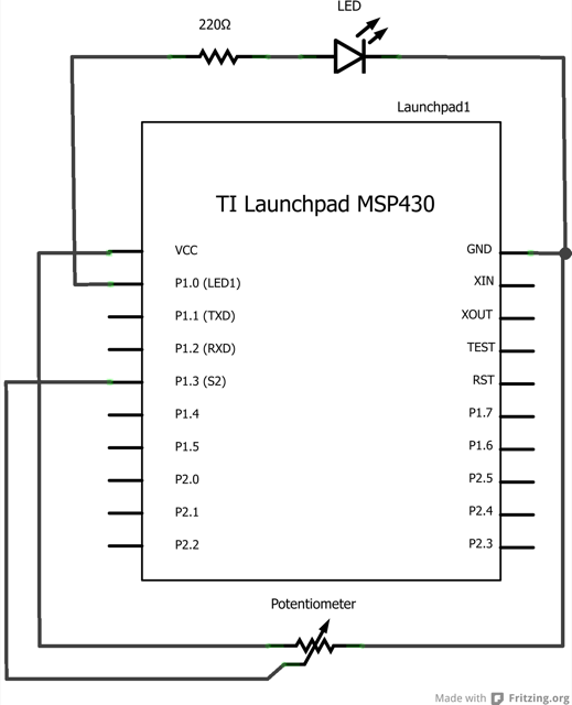
A potentiometer is a simple knob that provides a variable resistance, which you can read into the LaunchPad board as an analog value. In this example, you’ll connect a potentiometer to one of the LaunchPad’s analog inputs to control the rate at which the built-in LED on pin 2 blinks.
MSP430 LaunchPad
Potentiometer
Built-in LED on pin 2
Connect three wires to the LaunchPad board. The first goes to ground from one of the outer pins of the potentiometer. The second goes from ~3 volts to the other outer pin of the potentiometer. The third goes from analog input A3 to the middle pin of the potentiometer.
For this example, it is possible to use the LaunchPad board’s built in LED attached to pin 2. To use an additional LED, attach its longer leg (the positive leg, or anode), to digital pin 2, and it’s shorter leg (the negative leg, or cathode) to the ground (gnd) pin next to pin 2. Because of the low amount of current coming from digital pin 2, it is not necessary to use a current limiting resistor in this particular case.
In the beginning of this program, the variable sensorPin is set to to analog channel A3, where your potentiometer is attached, and ledPin is set to digital pin 2. You’ll also create another variable, sensorValue i to store the values read from your sensor.
The analogRead() command converts the input voltage range, 0 to ~3 volts, to a digital value between 0 and 1023. This is done by a circuit inside the LaunchPad called an analog-to-digital converter or ADC.
By turning the shaft of the potentiometer, you change the amount of resistance on either side of the center pin (or wiper) of the potentiometer. This changes the relative resistances between the center pin and the two outside pins, giving you a different voltage at the analog input. When the shaft is turned all the way in one direction, there is no resistance between the center pin and the pin connected to ground. The voltage at the center pin then is 0 volts, andanalogRead() returns 0. When the shaft is turned all the way in the other direction, there is no resistance between the center pin and the pin connected to ~3 volts. The voltage at the center pin then is ~3 volts, and analogRead() returns 1023. In between, analogRead() returns a number between 0 and 1023 that is proportional to the amount of voltage being applied to the pin.
That value, stored in sensorValue, is used to set a delay() for your blink cycle. The higher the value, the longer the cycle, the smaller the value, the shorter the cycle.
/*
  Analog Input
  Demonstrates analog input by reading an analog sensor on analog channel A3 and
  turning on and off a light emitting diode(LED)  connected to digital pin 2.
  The amount of time the LED will be on and off depends on
  the value obtained by analogRead().

  The circuit:
  * Potentiometer attached to analog channel A3
  * center pin of the potentiometer to the analog pin
  * one side pin (either one) to ground
  * the other side pin to ~3V
  * LED anode (long leg) attached to digital output 2
  * LED cathode (short leg) attached to ground

  * Note: MSP430 LaunchPad has a built-in LED attached
    to pin 2 on the board, the LED is optional.

  Created by David Cuartielles
  modified 27 Mar 2013
  By Adrian Fernandez

  This example code is in the public domain.

*/

int sensorPin = A3;    // select the input pin for the potentiometer
int ledPin = 2;      // select the pin for the LED
int sensorValue = 0;  // variable to store the value coming from the sensor

void setup() {
  // declare the ledPin as an OUTPUT:
  pinMode(ledPin, OUTPUT);
}

void loop() {
  // read the value from the sensor:
  sensorValue = analogRead(sensorPin);
  // turn the ledPin on
  digitalWrite(ledPin, HIGH);
  // stop the program for  milliseconds:
  delay(sensorValue);
  // turn the ledPin off:
  digitalWrite(ledPin, LOW);
  // stop the program for for  milliseconds:
  delay(sensorValue);
}
Incorporate multiple analog signals into the program.
AnalogReadSerial:read a potentiometer, print it’s state to the serial monitor.
AnalogInOutSerial:read an analog input, map its values, and then use that information to dim or brighten an LED.
Fade:use an analog input to fade an LED.
Calibration:calibrating analog sensor readings.
Corrections, suggestions, and new documentation are very welcomed. They can be contributed to the energia website repository on Github.
The text of the Energia getting started and reference guides are licensed under a Creative Commons Attribution-ShareAlike 3.0 License. The Energia reference is based on the Wiring/Arduino reference. Code samples in the guide are released into the public domain.
Energia sketches are C/C++ based and compiled with the open-source compiler MSPGCC or arm-gcc-none-eabi. The Energia language comes from Wiring. The Energia environment is based on Processing and includes modifications made by Wiring and Arduino.
© Energia